
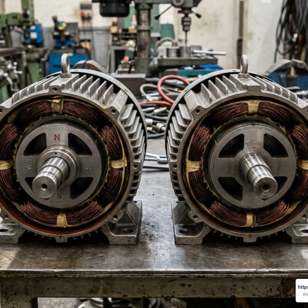
3600 RPM Motor vs. 1800 RPM Motor: Fundamentals and Applications
Understanding the mechanical differences between a 2-pole 3600 RPM motor and a standard 4-pole 1800 RPM motor is essential when designing or replacing industrial drive systems. Operating on a standard 60 Hz AC electrical grid in North America, standard induction motors convert electrical energy into mechanical rotation based on the physical design of their internal magnetic fields.
A 2-pole motor features two magnetic poles per phase, allowing the internal magnetic field to complete one full revolution per electrical cycle. Because 60 Hz power alternates 60 times per second (3,600 times per minute), the motor attempts to spin at a matching 3600 RPM. By contrast, a 4-pole motor splits that same electrical input across four magnetic poles, causing the shaft to rotate at half the speed (1800 RPM).
Because horsepower is directly proportional to torque multiplied by rotational speed, a 3600 RPM motor delivers high power density in a smaller physical footprint. Operating at direct-drive speeds eliminates the weight, cost, and maintenance requirements of intermediate gearboxes, belts, and pulleys when paired with high-speed machinery.
Synchronous Speed Math and 2-Pole Design
The relationship between power frequency, pole count, and motor speed is defined by the standard synchronous speed formula:
$$text{Synchronous RPM} = frac{120 times text{Frequency (Hz)}}{text{Number of Poles}}$$
Plugging in standard 60 Hz power and a 2-pole stator design yields:
$$text{Synchronous RPM} = frac{120 times 60}{2} = 3600text{ RPM}$$
However, standard AC induction motors do not run at exact synchronous speed when carrying a physical load. To produce rotational force (torque), the rotor must turn slightly slower than the rotating stator magnetic field. This speed difference is known as rotor slip.
Under actual full-load conditions, a nominal 3600 RPM motor typically operates between 3450 RPM and 3550 RPM. For example, a standard 30 HP industrial unit might feature a full-load rating of 3550 RPM, reflecting roughly 1.4% rotor slip under maximum mechanical resistance.
Applications and Advantages of the 3600 RPM Motor
High-speed 2-pole motors are ideal for equipment engineered to turn fast to create fluid pressure, velocity, or high surface speeds. Common applications include:
- Centrifugal Pumps: High shaft speeds build kinetic energy in dynamic fluid impellers, generating maximum head pressure without requiring secondary gear increasers. Explore specialized industrial drive options for high-speed pumps.
- Air Compressors: Rotary screw and centrifugal compressors depend on high rotation rates to compress large volumes of gas efficiently.
- Industrial Blowers & High-Speed Fans: Moves huge volumes of air in HVAC, ventilation, and pneumatic conveying systems.
- Machine Tools: Powering spindles, grinding wheels, and precision saws where elevated rim speed improves cutting finishes.
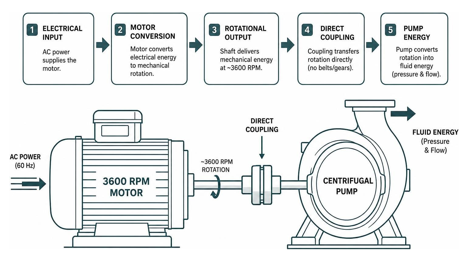
Key Specifications for Choosing a 3600 RPM Motor
Selecting the correct 3600 RPM motor requires matching the unit’s mechanical and electrical nameplate parameters to the operating environment. Standard industrial options span horsepower ratings from fractional 0.25 HP units up to 200 HP continuous-duty models (and beyond in specialized process designs).
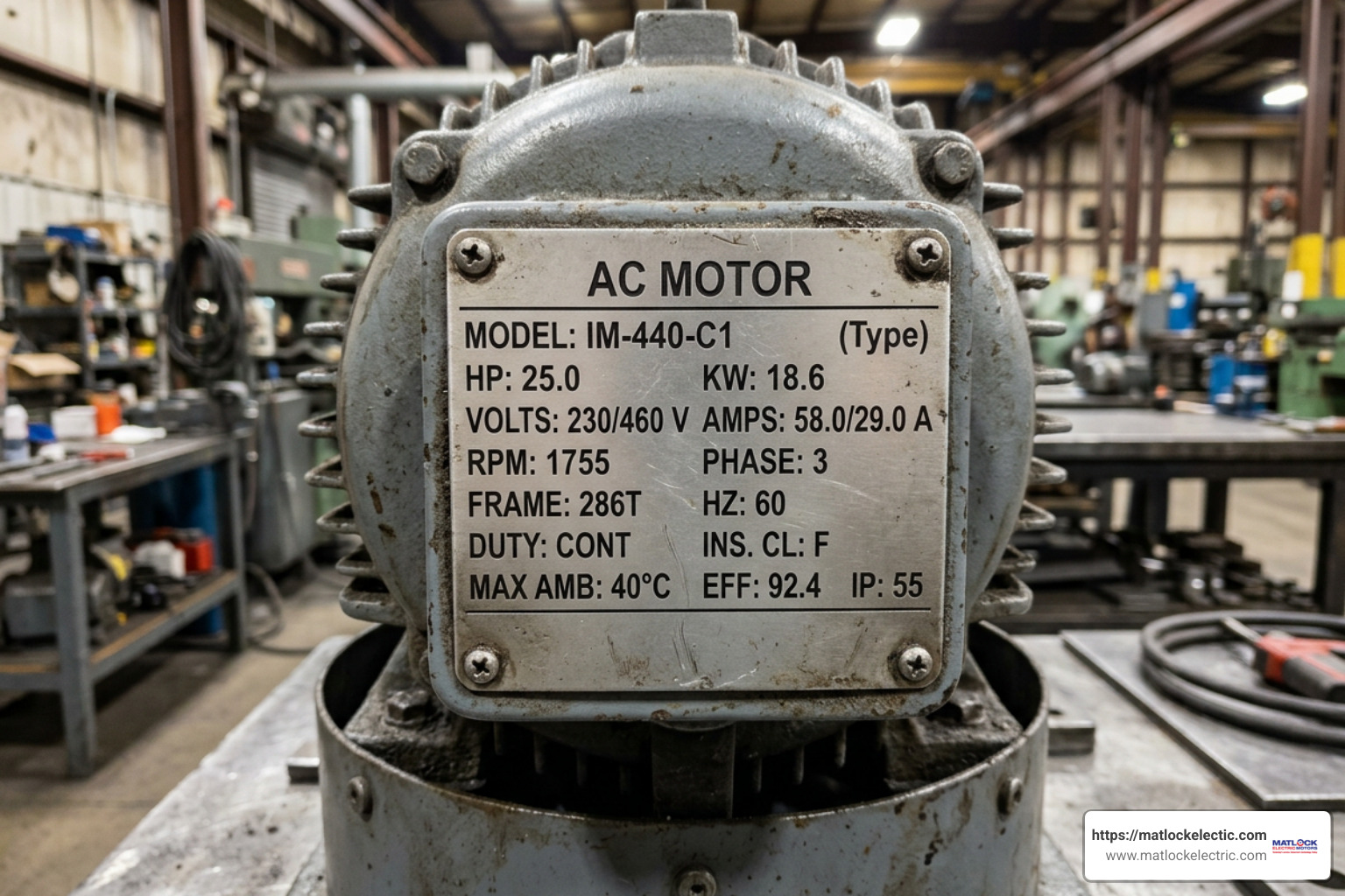
Single-Phase vs. Three-Phase Performance
Electrical supply configuration dictates motor performance, starting capability, and physical sizing:
Single-phase models operating on standard 208V or 230V lines are common where utility three-phase power is unavailable. For instance, a 3 HP, single-phase 3600 RPM motor in a 56H frame draws approximately 12.7 full-load amps at 230V and weighs around 41 lbs.
Three-phase motors operating on 230V, 460V, or 575V offer superior electrical efficiency, continuous operation thermal limits, and smoother running torque.
Enclosure Types and Environmental Protection
Enclosure selection determines how effectively an electric motor withstands moisture, airborne dirt, washdown chemicals, and explosive vapors:
- ODP (Open Drip-Proof): Features open ventilation slots directed to prevent liquid drops from falling inside. Best for clean, indoor, dry environments.
- TEFC (Totally Enclosed Fan-Cooled): Seals internal windings against outside air while blowing air over the outer housing using an external shaft fan. The standard choice for general industrial service.
- TENV (Totally Enclosed Non-Ventilated): Air-tight design operating without an external cooling fan, relying entirely on surface radiation. Ideal for washdown areas where fan housings could harbor bacteria.
- XPFC (Explosion-Proof Fan-Cooled): Engineered with heavy cast enclosures to contain internal explosions without igniting surrounding explosive hazardous gases or dust (Class I/II ratings).
Frame Sizes, Shaft Dimensions, and Mounting Configurations
Standardized NEMA frame designations ensure physical interchangeability between motor manufacturers. Frame numbers directly dictate shaft height, mounting hole centers, and shaft diameter.
Note: The “TS” suffix (e.g., 286TS) indicates a short-shaft motor specifically engineered for direct-coupled high-speed connections to limit bearing stress.
Mounting styles vary based on driven equipment geometry:
- Rigid Foot Mount: Standard bottom mounting feet bolted down to a flat steel base plate.
- C-Face Mount: Features a machined face plate with threaded holes for close-coupling directly to pumps or gearboxes.
- D-Flange Mount: Utilizes an oversized mounting flange with unthreaded clearance holes for bolt-through installation from the rear.
- Vertical Mount: Designed with specialized thrust bearings to support the weight of vertical turbine pumps or mixers.
Efficiency Standards, Duty Ratings, and Service Factors
Continuous-duty high-speed motors consume their purchase price in electricity many times over during their operational lifespan. Specifying proper efficiency classes and overload margins protects plant profitability and prevents premature winding failure.
NEMA Premium Efficiency and Operational Costs
Industrial standards (EISA 2010 / NEMA Premium / IE3) dictate strict efficiency thresholds for 2-pole motors. Higher operational speeds create windage and friction losses inside the frame, making efficient electrical designs critical.
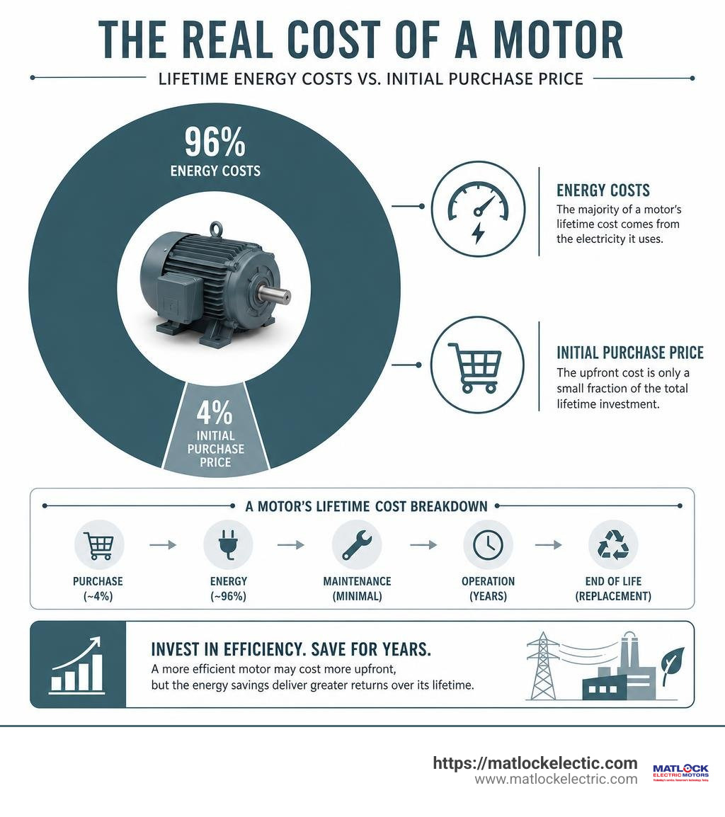
A standard 30 HP, 3600 RPM, 460V motor in a 286TS TEFC frame achieves a full-load efficiency rating of 91.7%. Operating continuously across multiple shifts, a NEMA Premium rated motor reduces facility grid draw, lowers thermal output, and slashes utility bills compared to legacy standard efficiency models. If you are reviewing facility equipment upgrades, explore current availability in new electric motor sales.
Standard-Duty, Severe-Duty, and Specialty Enclosures
Standard cast-iron or aluminum frames perform reliably in routine factory automation. However, demanding process plants require elevated motor specs:
- Severe-Duty (IEEE 841): Built using high-rigidity FC200 cast iron, dynamic rotor balancing to under 0.08 in/sec vibration limits, non-contact Inpro/Seal VBX bearing isolators, and IP56 water/dust ingress protection.
- Stainless Steel Washdown: Designed for food processing and pharmaceutical facilities. Units like a 2 HP, 56C frame stainless steel 3600 RPM motor withstand harsh caustic chemicals and daily high-pressure washdowns without rusting.
Impact of Service Factor on Longevity
Service Factor (SF) indicates a motor’s capacity to handle continuous or intermittent loads above its rated horsepower without thermal damage:
- 1.0 Service Factor: The motor should not be operated above its nominal horsepower rating.
- 1.15 Service Factor: Standard for most industrial 3600 RPM motors. Provides a 15% continuous thermal headroom buffer (e.g., a 30 HP motor can run safely at 34.5 HP under normal ambient temperatures).
This added thermal margin helps absorb voltage fluctuations, elevated ambient heat, and temporary mechanical overloads without degrading internal winding insulation.
VFD Integration and High-Speed Speed Control
Connecting a 3600 RPM motor to a Variable Frequency Drive (VFD) enables precise process tuning, soft starting, and energy savings. However, adjusting 2-pole motor speed requires careful engineering attention to drive parameters and mechanical design constraints.
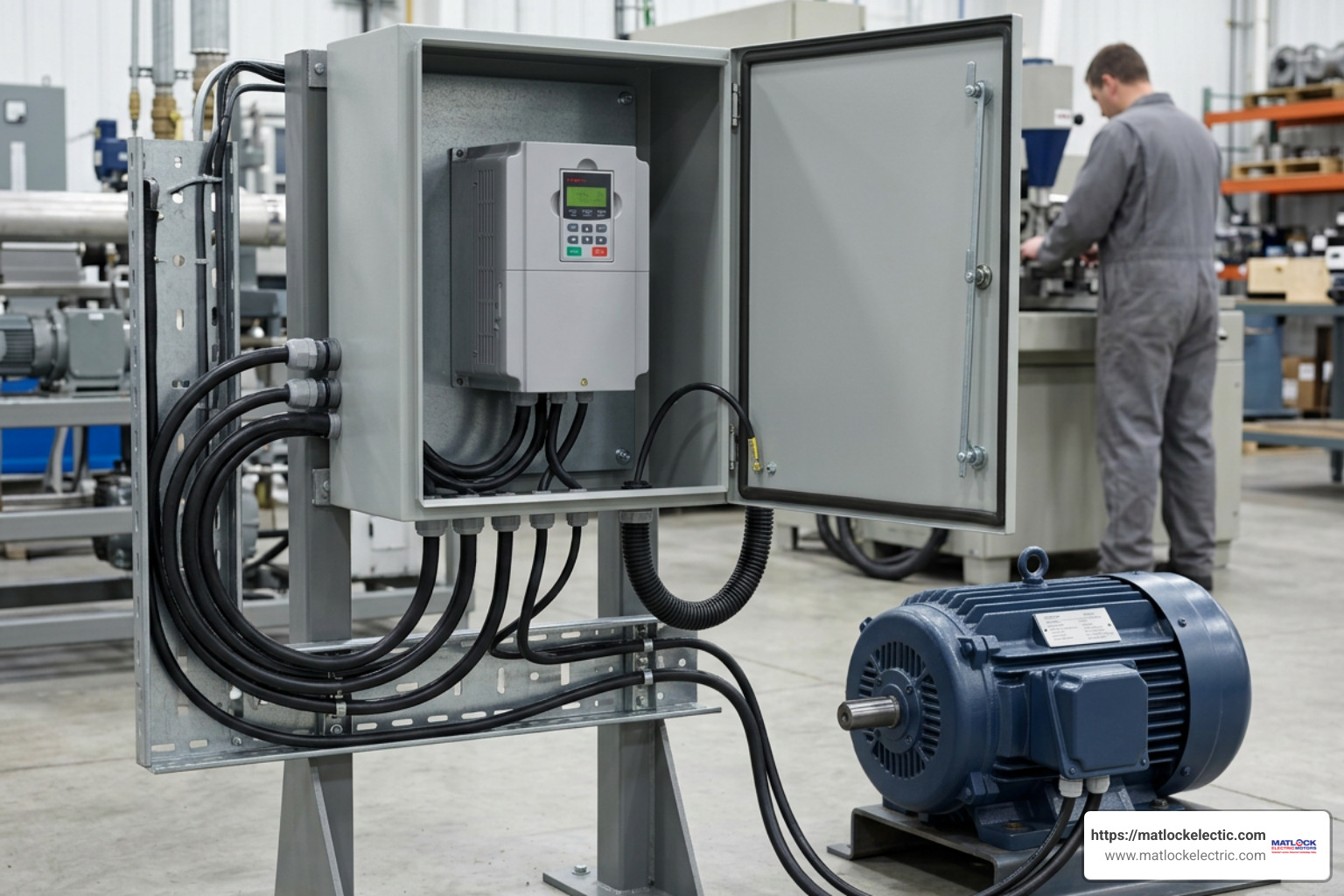
VFD Speed Control and Overdriving a 3600 RPM Motor
A VFD controls motor speed by varying the output frequency sent to the stator windings. While running a 2-pole motor from 0 to 60 Hz provides predictable linear torque, attempting to “overdrive” a motor beyond 60 Hz (e.g., pushing an 1800 RPM motor up to 3600 RPM by running the VFD to 120 Hz) introduces significant electrical and mechanical challenges.
- Torque Loss in Constant HP Region: Above 60 Hz base frequency, line voltage saturates at maximum supply output. Because the drive cannot increase voltage proportionally with frequency, the Volts-per-Hertz (V/Hz) ratio drops. This forces the motor into a constant horsepower region where available output torque decreases linearly. Running a standard motor at 120 Hz results in a 50% or greater reduction in peak torque.
- Mechanical Bearing & Rotor Limits: NEMA MG1 standards establish mechanical overspeed limits for motor rotors and internal cooling fans. Overdriving a standard motor can trigger high-frequency vibration, bearing overheating, or fan failure.
- Thermal Management: At lower speeds under VFD control, shaft-mounted fans produce far less airflow. Heavy loads at reduced speeds may require separately powered blowers or dedicated motor thermal monitoring.
For facilities managing automated motor controls, learn more about system integration through our drives and controls team.
Frequently Asked Questions About High-Speed Motors
What is the actual full-load speed of a 3600 RPM synchronous motor?
While the theoretical synchronous speed of a 2-pole motor on 60 Hz power is exactly 3600 RPM, the actual full-load output speed is lower due to rotor slip. Most industrial 3600 RPM induction motors operate between 3450 RPM and 3550 RPM under full load.
For instance, a standard 30 HP severe-duty motor rated at 3550 RPM exhibits 50 RPM of slip, which is necessary to generate its rated 44.4 ft-lbs of continuous full-load torque.
Why does motor torque decrease when running above 60 Hz on a VFD?
When a VFD increases motor output frequency past 60 Hz, the incoming line voltage reaches its maximum electrical ceiling (such as 460V). Because the drive can no longer increase voltage alongside frequency, the motor’s magnetic field weakens.
This transitions the motor from a constant torque regime into a constant horsepower regime, causing available output torque to drop inversely with speed. At 120 Hz, available shaft torque is reduced by at least 50%.
What frame sizes are most common for fractional and integral 3600 RPM motors?
Conclusion
Choosing the right 3600 RPM motor means striking the right balance between rotational speed, torque capacity, thermal protection, and physical mounting specs. Whether you are running centrifugal pumps, high-velocity blowers, or precision machine spindles, selecting the right enclosure, efficiency class, and service factor protects your production uptime.
When high-speed motors encounter bearing wear, insulation breakdown, or mechanical vibration, expert testing and reconditioning restore reliable plant performance. Discover how our experienced technicians handle comprehensive ac repairs to keep your critical drive equipment running at peak speed.
For a broader overview of how motor architectures differ across industrial installations, read our comprehensive guide on AC and DC Motor Differences. If you need assistance selecting, upgrading, or repairing your facility’s high-speed drive systems, reach out to the technical experts at Matlock Electric today.